What is Software Architecture and What is the common architectures? - Part 1
Mohamed Kassem | February 03, 2021

In this article, we will discuss the ways these architectures are represented, both in UML and other visual tools. We will introduce the most common architectures, their qualities, and tradeoffs. We will talk about how architectures are evaluated, what makes a good architecture, and an architecture can be improved. We’ll also talk about how the architecture touches on the process of software development.
Table of Content
-
Architecture overview
- Kruchten’s 4 + 1 Model View (4 plus 1 view model)
- UML Component Diagram
- UML Package Diagram
- UML Deployment Diagram
- UML Activity Diagram
-
Language-based Systems
- Object-Oriented Architectural Style
- Main Program and Subroutine Architectural Style
-
Repository-based Systems
- Data Centric Software Architecture
-
Layered Systems
- N-Tier Architecture
Architecture overview
Software Architecture is the fundamental design of the software system. It defines what elements are included in the system, what function each element has, how each element related to another. In plain text, it is the big picture (overall structure) of the whole system.
Some considerations that the architect will consider while planning the structure of the system:
- What will the system be used for?
- Who will be using the system?
- What qualities matter most to them?
- Where will the system run?
Why do we need software architecture?
- Having a clear design of the system as a starting point helps to provide the basis for developers to follow, each developer will then know that needs to be implemented and how things relate to meet the desired needs efficiently.
- Higher productivity for your software team, as a well-defined structure helps to coordinate work, implement individual features, or guide discussions on potential issues.
- A clear architecture will help to achieve quality in your software, with a well-design structure using principles like separation of concerns, the system will be easier to maintain and reuse.
Stakeholders are the people who have an interest in the software system or people who will use the system. So how software architecture helps people like developers, end users, project managers, and clients?.
- Software Developers ⇒ Software architecture helps developers create and evolve software by providing strong direction and organization on what needs to be done or built.
- Project Managers ⇒ Software architecture provides useful information to help them identify possible risks, manage the project successfully and understand task dependencies.
- Clients ⇒ Clients make an important decision about the system like funding if there a good architecture to understand what they are paying for and their needs are met.
- End Users ⇒ They care that if the app “works well” for them
Kruchten’s 4 + 1 Model View (4 plus 1 view model)
There are several considerations to capture the complete behavior of the software system.
- Logical View ⇒ One consideration is the functionality of the software that satisfies what a client wants, which call Logical View which focuses on the functionality of the system and the objects found within it.
- Process View ⇒ Another consideration is how the software executes? including characteristics like the efficiency of the system, performance, and scalability called Process View which focuses on the process of implementing the Logical View.
- Development View ⇒ The Implementation, the structure, and its the programming languages of your software can be considered as Development View.
- Physical View ⇒ The physical components that are needed to deploy like one server for database and other hosts for your web clients, Physical view plan how these elements interact to deploy the system correctly.
Without knowing what the system achieves for its users, it would be difficult to detail these views.
These views together are from Kruchten’s 4 + 1 View Model, that does follow these 4 views and perspectives to create software architecture instead of one single perspective of the system.
- Logical View ⇒ focuses on achieving the functional requirements of a system and the services that should be provided to end users. You can create UML Class Diagram that illustrates the objects in the logical view and also describes database schemes.
- Process View ⇒ focuses on achieving the Non-functional requirements to specify the qualities for the system like performance and availability. UML Sequence Diagram help for illustrating the methods and how they are executed and their order, UML Activity Diagram can illustrate the processes or activities for a system
- Development View ⇒ focuses on details of software development and considers elements like programming languages, libraries, and tools, also besides code it handles project management details like scheduling, budgets and work assignments.
- Physical View ⇒ focuses on handles logical, process and development views in different nodes or hardware for running the system, a UML Deployment Diagram express how the pieces of a system are deployed into hardware.
Not all software architectures need to be documented using 4 + 1 view model, if any of the views is useless so can be ignored.
UML Component Diagram
Component diagram is high-level structure used to visualize how a system’s pieces interact and what relationships they have among them. Focus on the components of a system and interactions between them, not their methods and implementations.
This diagram is concerned with the components of a system. Which components are defined as independent encapsulated units within a system, each component provides and an interface for other components to interact with it including third-party libraries.
Diagram Components Relationship
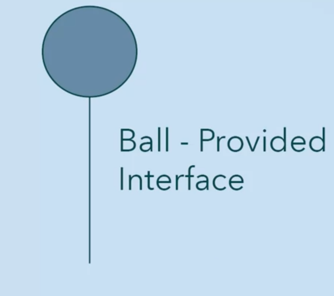
- Ball Connector: displays a provided interface
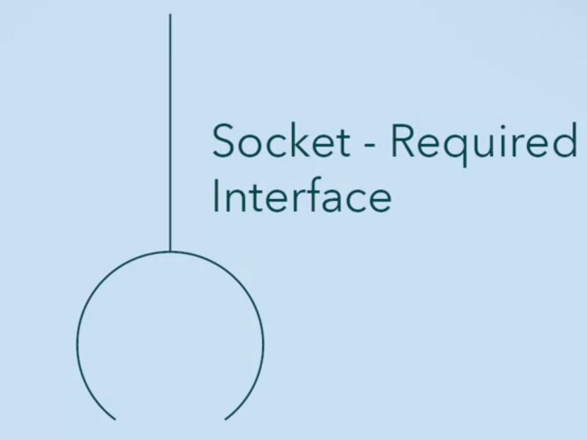
- Socket Connector: displays a required interface (component expects a interface)
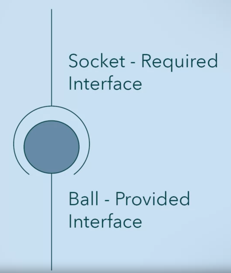
- Relationship shows that the component provided interface matches another component’s required interface
Steps to build a Component Diagram
- Define the main objects used in the system
- Define the relevant libraries you need for your system
- Define the relationships between these components
Example of a component diagram for a video game system.

UML Package Diagram
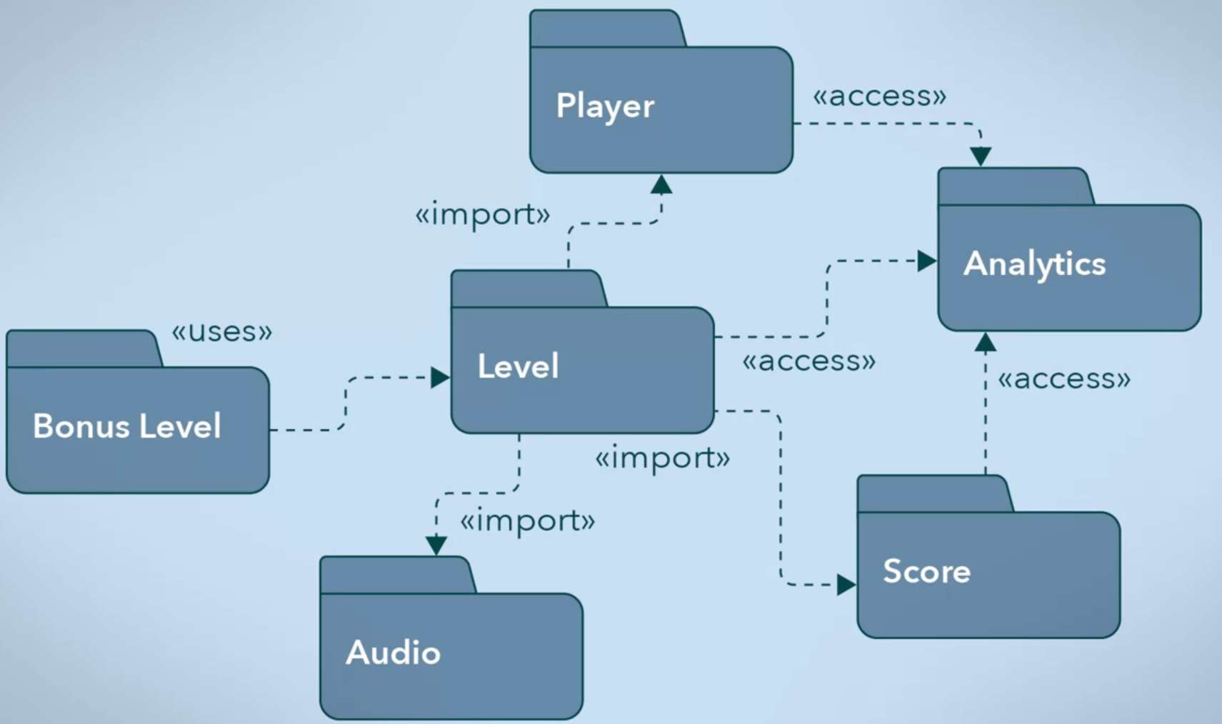
A package groups together elements (data, classes, functionality) of your software that are related. It defines as a Namespace for the elements it contains.
Packages diagram show packages and the dependencies between them to organize your completed system into packages of related elements.
Package Diagram components
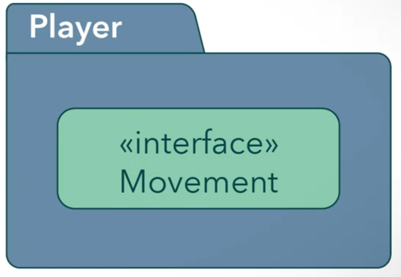
- Tabbed folder (if the package don’t have any elements, package name writes in the center of folder)
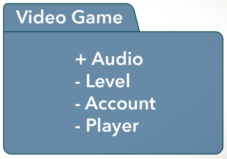
- Importing and Merging other packages into packages. Dependencies like
<import>= public import,<access>= private import ⇒ means one package requires help from functions of another package.<merge>= merging two packages into a single package.<uses>= the package need the full implementation of another package
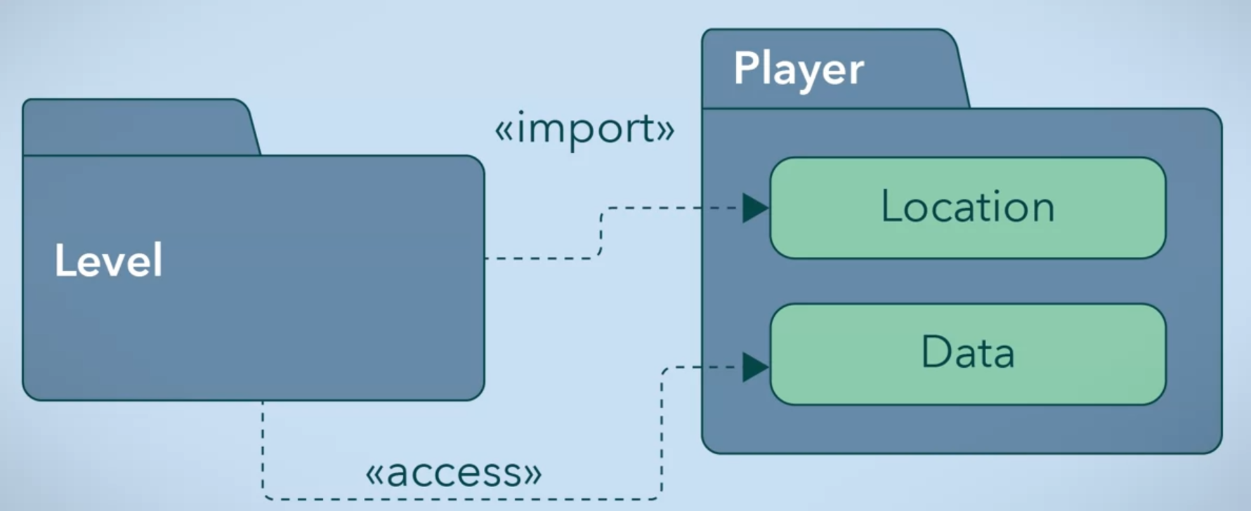
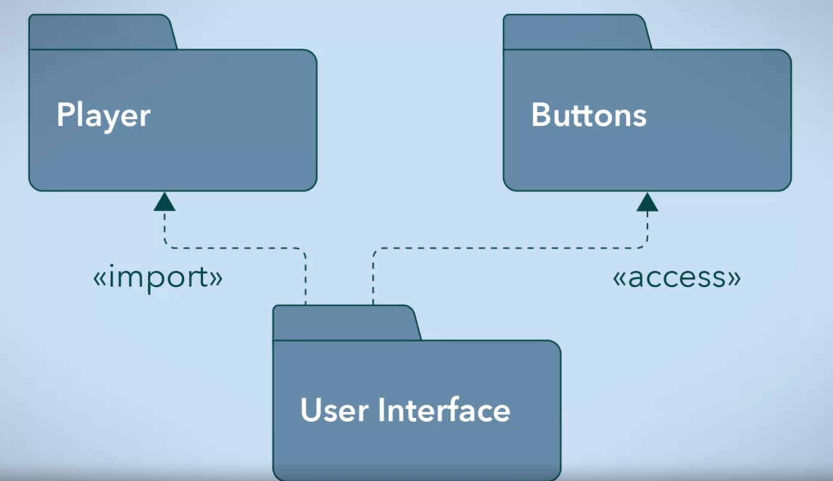
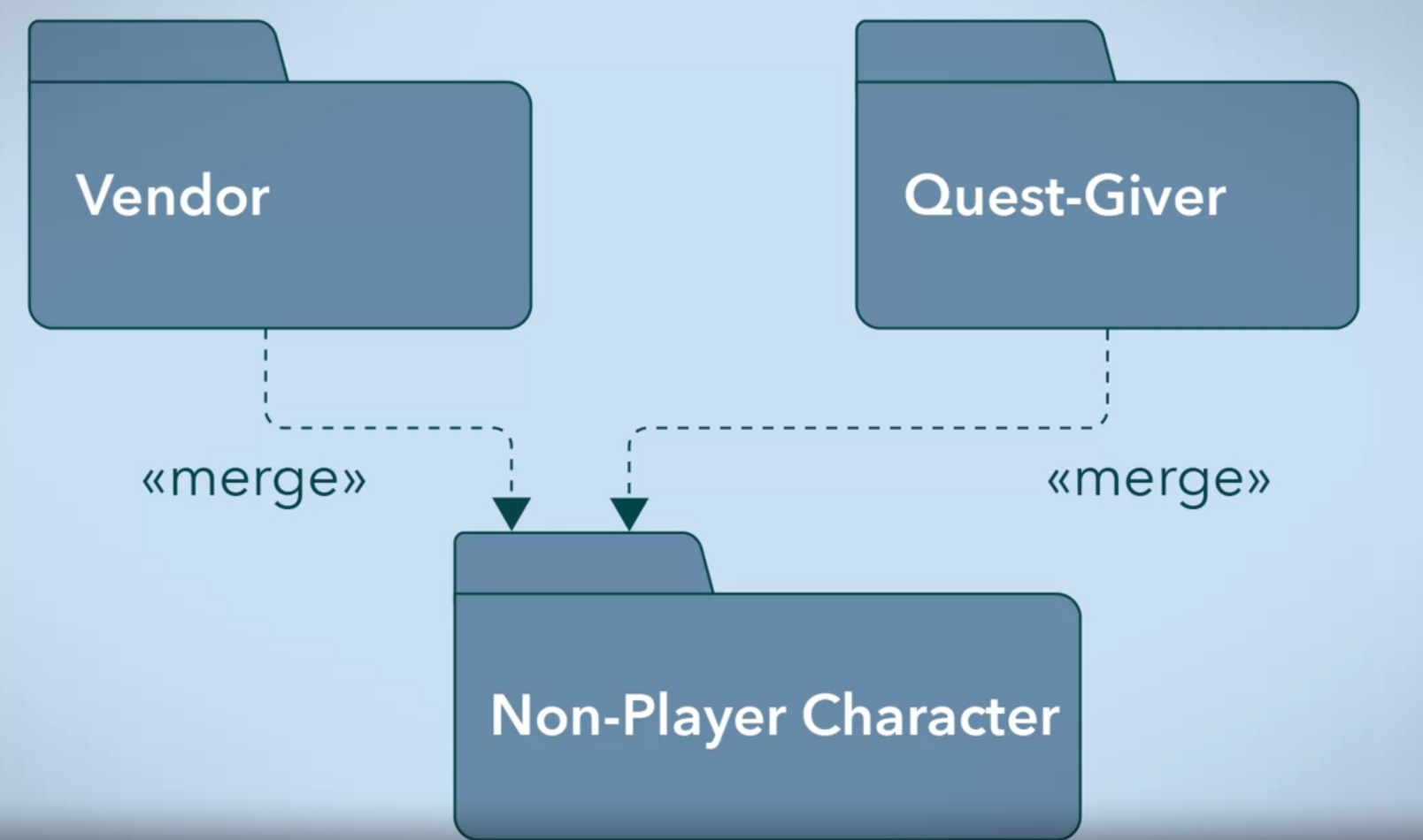
Example of UML Package diagram
UML Deployment Diagram
Software release involves separate libraries, an executable, an installer, configuration files and other different pieces. Once the environment of all pieces are sit, you would use UML Deployment Diagram to visualize these deployment details for a software system.
UML Deployment Diagram deal with Artifacts. Artifact which are a physical result of the development process, For example of video game would be an executable to run the game, an installer, audio libraries and multimedia assets
Two types of deployment diagram
-
Specific Level Diagram
Which gives an overview of artifacts and deployment targets without referencing details like machine names. It focuses on a general overview of your deployment.
-
Instance Level Diagram
Is a much more specific diagram, which can map an artifact to a deployment target. It can identify machines and hardware devices. This approach is used to highlight the differences in deployments amount development, staging, and release build.
UML Deployment diagram components
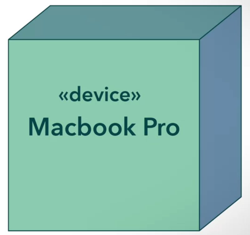
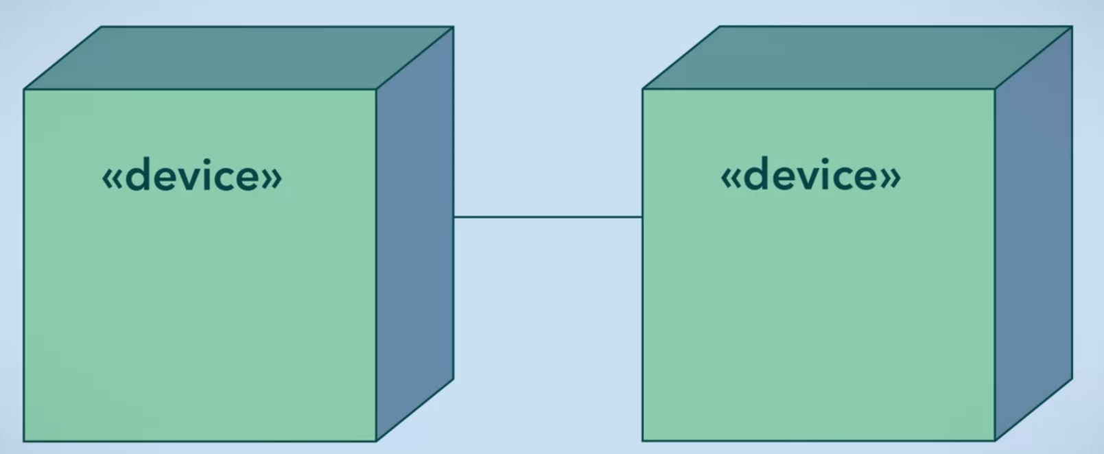
- Node: is deployment target that contains artifacts for execution, its the hardware
<<device>>.

- Relationship between deployment targets, this relationship between nodes means that there is a communication path (software or protocol) between them.
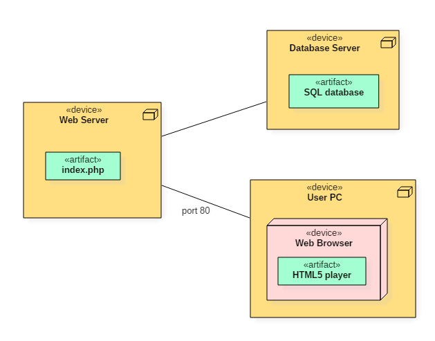
<<manifests>>relationship between artifacts and which component complied and produce it. Which Player.Class is the encapsulated unit that contains all of the functionality of a player.

Example of UML Deployment diagram
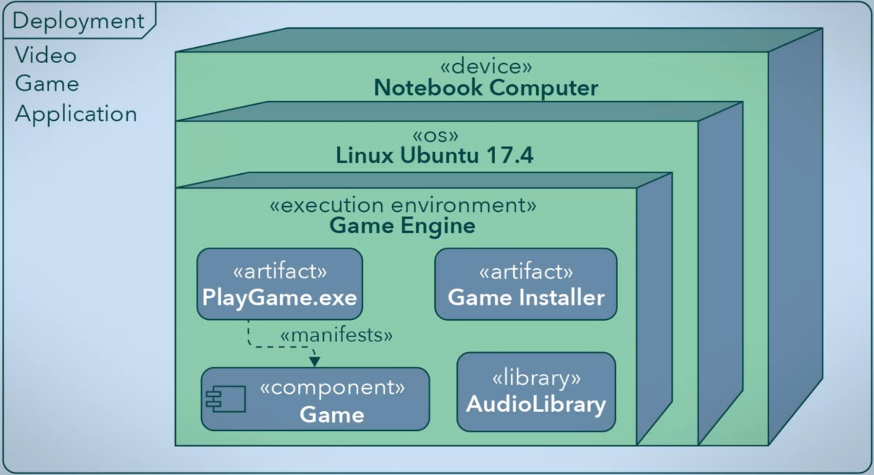
Deployment Diagram gives a high level look at the artifacts, libraries, main components, machines, and devices that your application needs to run.
UML Activity Diagram
In this diagram, you represent the control flow from one activity to another in a software system, activities are actions that when completed cause another action to start/execute. For example these actions can edit objects or create new objects to drive your application forward. The purpose of this diagram is to capture the dynamic behavior of the system.
To create an Activity Diagram:
- Identify the activities (actions) performed by the system.
- Identify the conditions of these activities.
UML Activity Diagram Components
- Start and End nodes must begin (initialize) and end (final) your diagram with them.

- Intermediate activities that identify to change the application state before ends.

- Decision node that had the condition to determine which outcomes as the next activity.
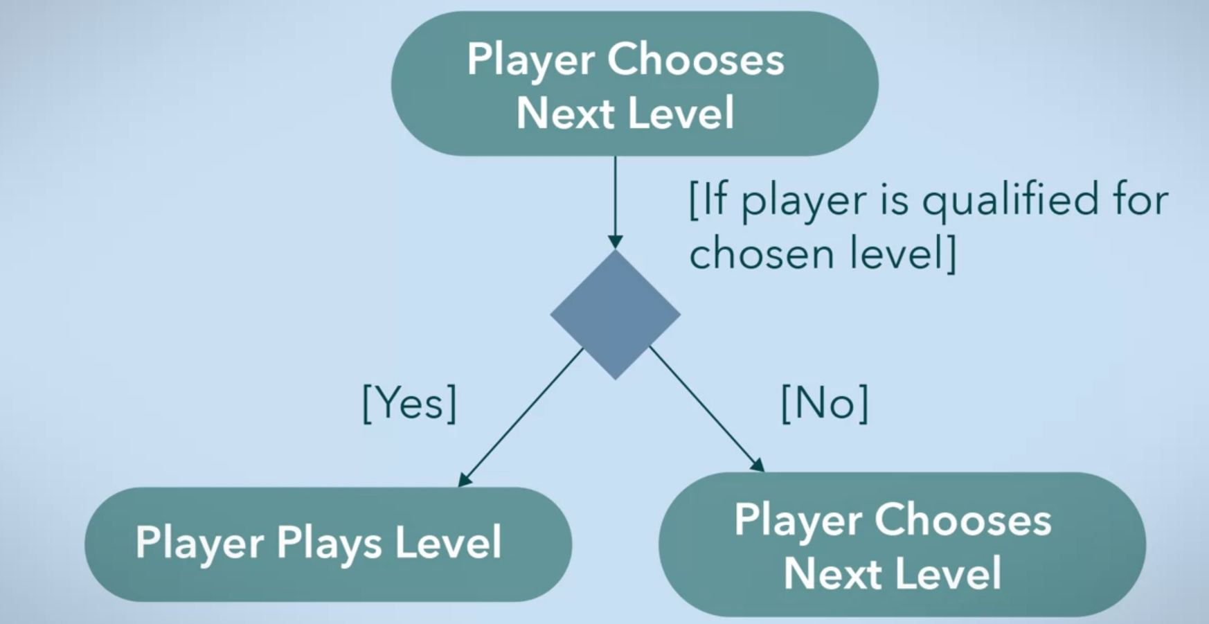
Example of UML Activity Diagram of video game
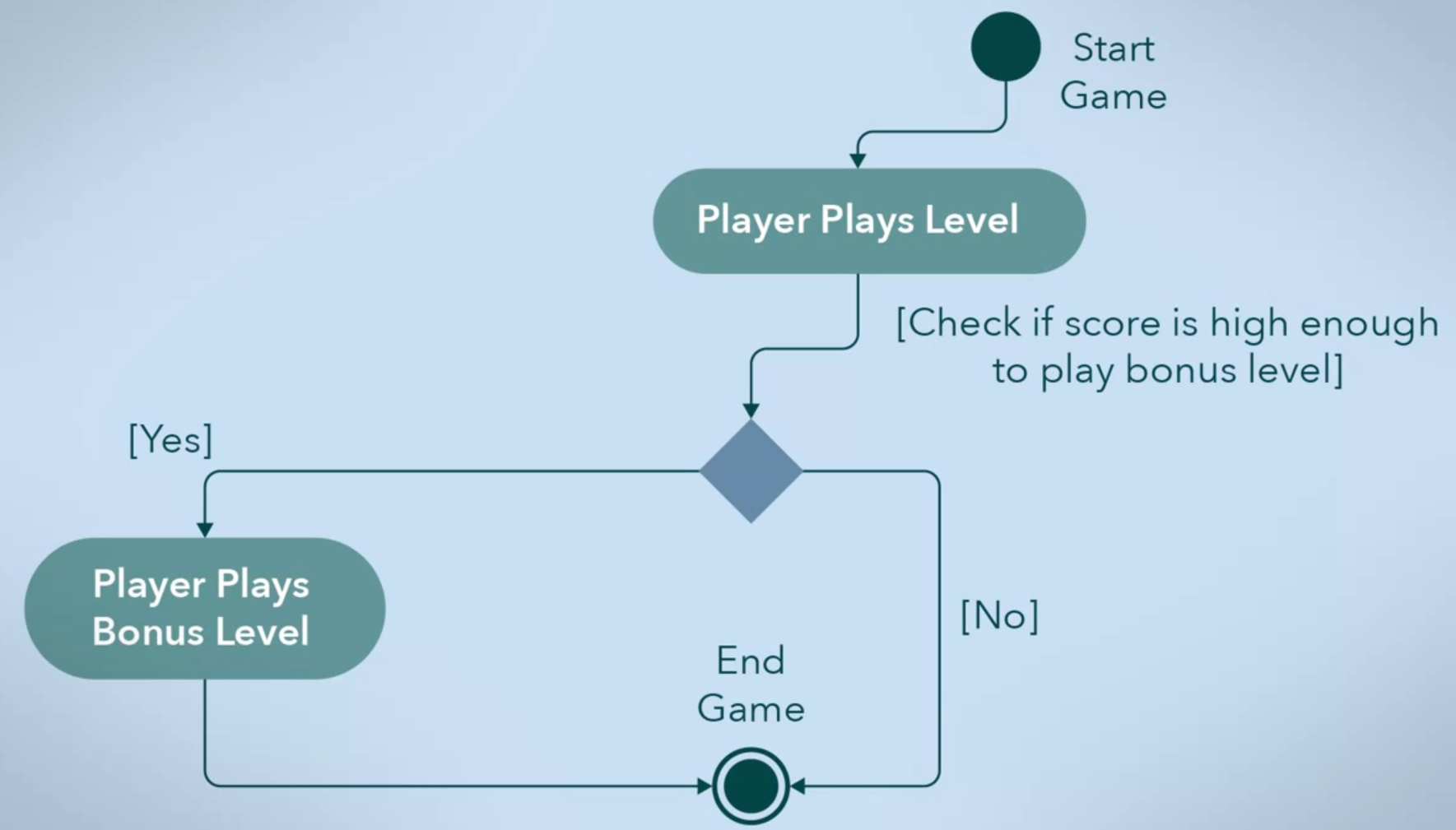
Also Activity diagrams allow the mapping of activities that happen in parallel and join in a single flow after ended. Like if a level ends in a video game, the soundtrack flow will end at the same time as the play flow.
Language-based Systems
The Programming paradigm of the language will affect the architectural system of the system, Each programming paradigm has its own constructs, principles, design patterns, and their use to shape the system you create.
One of these styles of the language-based system is Object-Oriented Architectural Style which results from the object-oriented programming paradigm and uses object-oriented approach in development.
Object-Oriented Architectural Style
object-oriented principles were explored:
- Abstraction that simplify a concept by ignoring unimportant details.
- Encapsulation that bundles data and functions into a self-contained object, so other objects can interact with it through an exposed interface.
- Decomposition which allows you to break up a whole problem into smaller, distinct parts.
- Generalization that allows you to factor out conceptual commonalities.
object-oriented Design Patterns were explored:
- Creational patterns that guide the creation of new objects.
- Structural patterns that describe the relationships between.
- Behavioral patterns that focus on how objects perform work individually or as a group to accomplish something.
These elements together will lead to an object-oriented architectural style for the system. This style focused on the data called Abstract Data Types which can be represented as a class the defines to organize data attributes in a meaningful way along with their associated methods.
Object-oriented refers to a system composed of objects where each object is an instance of a class (the type of object is its class), objects interact with each other through the use of their methods. object-oriented programming paradigm allows inheritance, which means one class can be an extension for another class. The classes within the system will determine the overall structure of the system.
Main Program and Subroutine Architectural Style
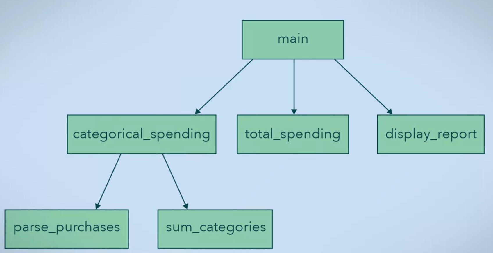
Main Program and Subroutine Architectural Style follow from the procedural programming paradigm, also C programming language follows this paradigm. This style focused on functions, when try to model your system you break up the overall functionality of the system into a main program and subroutines.
the following diagram shows how this style work which means the process of calls functions.
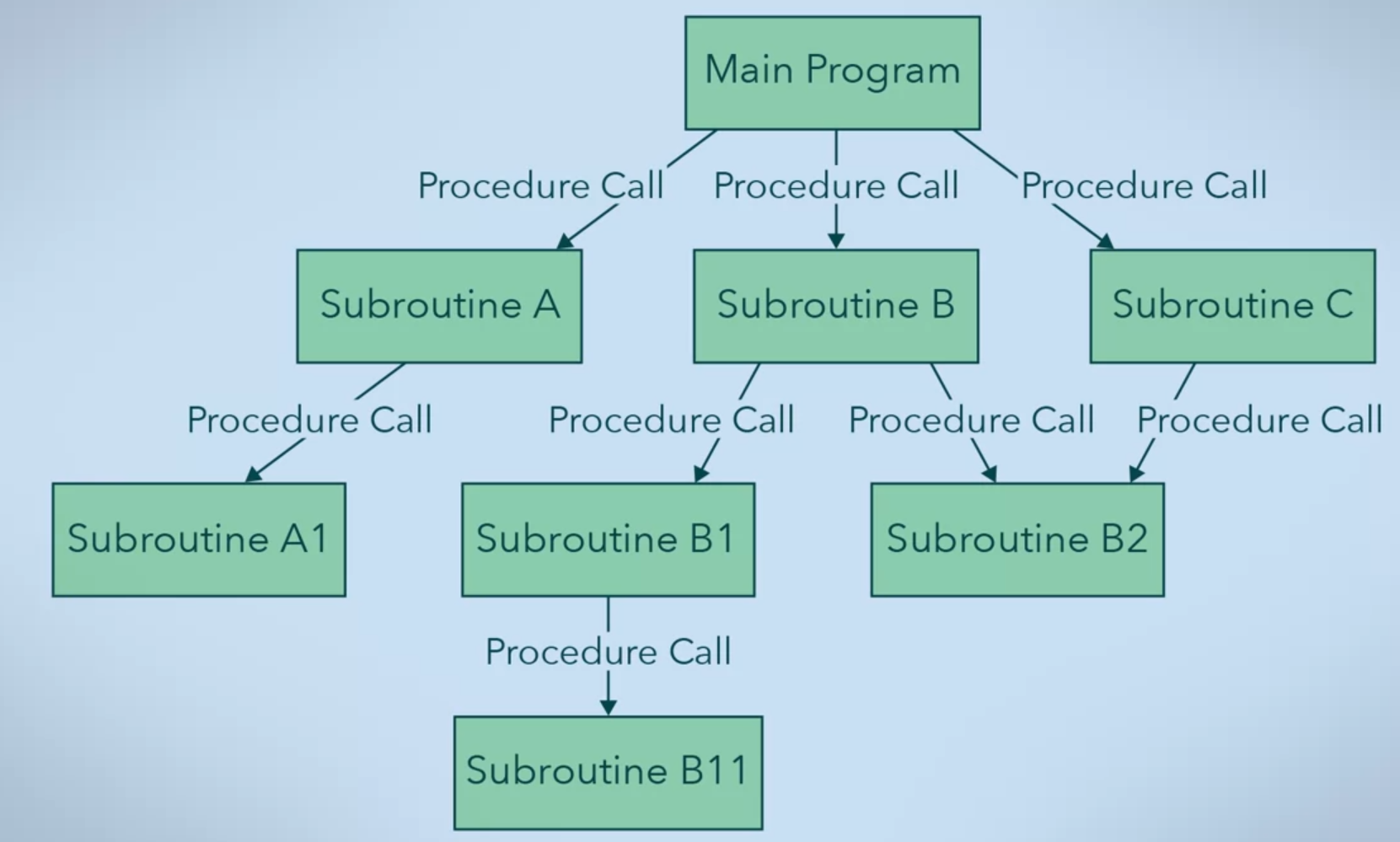
The main consideration of this style is the behavior of functions and how data moves through them, so procedural programming supports abstract data types. so this paradigm stored data as variables like object-oriented programming, However, inheritance is not supported. But this style is suitable for computation-focused systems.
The principle of this paradigm is “One entry, one exit per subroutine” so each subroutine have its own local variables and has access to all data within its scope, to get access to variable out of scope, you should pass the data as a parameters by value or by reference.
This architectural style focuses on modularity and function reuse. So you can think of them as black boxes meaning gives it a particular input, you always expect the same output. Further, library functions are easily integrated into programs
The issue of this approach is that subroutines may change data in unexpected ways, meaning a subroutine may be affected by data changes made by another subroutine at execution, throwing Runtime errors.
Example of spending report.
Repository-based Systems
As a software developer, any software architecture you create needs to be capable of sharing information between separate components and stored them in an organized database.
Data Centric Software Architecture
This architecture allows you to store and share data between multiple components, also helps to increase the maintainability, reusability and scalability of the system by integrating a shared data storage like databases.
Two components of this architecture
- Central Data: used to store and serve the information across all the components connected to it.
- Data Accessors: is any component that connects to the database, they make queries and transactions in the information stored in the database. Query the database to obtain shared system information. Save the new state of the system back into the database using transactions.
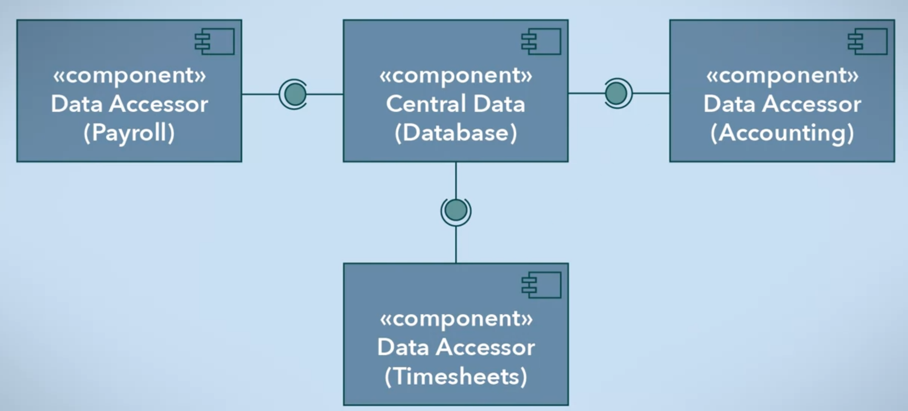
Database: is used to store data, it makes sure the data is accurate and consistent over its lifespan (data integrity), also makes sure the data will live on after a process has been terminated (data persistence). Relational Databases are a type of database that uses tables.
Relational Database uses Structured Query Language (SQL) to query or ask the database for information and perform transactions or tell a database to do something. Management and optimization of queries and transactions can be automated by Database Management System (DBMS).
Data accessor contains all the business rules required to perform its functions.
Advantages of Data Centric architecture over a basic object-oriented system.
- This architecture supports data integrity, data backup and data restoration through a database which can help if there are massive data loss, data corruption or data migrations.
- It reduces the overhead for data transfer between your data accessors, meaning the data accessor doesn’t to be concerned with talking to another.
- A system that can be easily scaled up, as data accessors are functionally independent, so additional features can be added with having to worry about affecting others.
- Central data components “live” on a separate server machine with sufficient disk storage dedicated to the database (centralized data repository), which allow for easier management of information
Disadvantages of Data Centric architecture
- Using centralized database, the system becomes heavily reliant on the central data component. If the data server goes offline, becomes unusable or contains corrupted data your entire system will be affected, for solving this issue there are data redundancies to replicate your data onto separate hard disks but the physical infrastructure can be expensive and costly to get your system back up and running again.
- Also your data accessors are dependent on what gets stored in the database. New data accessors need to build around the existing data schema. if there is no matching column or table for a specific data need, then the database cannot be used to save this data.
- It is difficult to change the existing data schema, which will affect your data accessors.
For Summary, The data centric software architecture allows you to:
- Store and manage large amount of data into a central data component. This increases your system’s stability, performance, reusability and maintainability.
- Separate the functionality of your data accessors, which makes it easier for you to maintain and scale your entire system.
- Facilitate data sharing between data accessors through database queries and transactions.
Layered Systems
In software applications the inner layer (bottom layer) providing services to the one outside it and vice versa. Each layer can communicate with its adjacent layers, For example the following diagram of school system. Principal layer interacts with Student layer through Teachers layer, Teach Layer interact with both layers Student and Principal, Also Student can interact with other students.
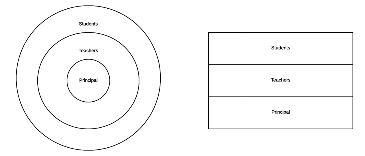
A layer is a collection of components that work together toward a common purpose. The components in a layer only interact with components in their own layer or adjacent layers.
Layering allows for separation of concerns into each layer, So many layered systems are split into Presentation, Logic and Data layers.
The Operating System (OS) for a computer is an example of layered system:
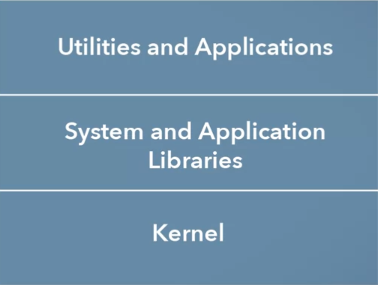
- Kernal: is the core of an OS, its main responsibilities it interfacing with the hardware and allocating resources like scheduling operations for the processor or reads the input from your mouse/keyboard.
- System and Application Libraries: is used to providing high-level functions (API) that the programs need to interface the kernel like functions for saving files or drawing graphics.
- Utilities and Applications: Utilities are tools included with the OS like command-line program or file browser, Applications are programs that installed by the user, this layer relies on the layer below to use system resources.
The most benefits and advantages of this layered structure.
- Is that users can perform complex tasks without understanding the layers below. Like programmers can create applications that rely on the libraries layer without needing direct knowledge of the kernel.
- Is that the different layers can be run at different levels of authorization, For example the Top layer is run in User Space which doesn’t have the authority to allocate system resources or communicate with hardware directly. this done by Sandboxing which improves the security and reliability of the kernel.
- Your design will be more loosely coupled and modular code. which Layered architecture follows the principle of Least Knowledge.
If you do replace a layer, you only have to ensure that its interface with the layer above is consistent with the previous implementation. So why use Layered Systems? because its powerful architecture and many organizations and solutions have a layered structure. And easily mapped to organize a solution of many problems and design complexity.
N-Tier Architecture
Tiers are similar to layers but often refer to components that are on physical machines. 3-Tier and 4-tier architectures are common used but any number is possible.
2-Tier Architecture
The relationship between 2-Tier is a Client/Server relationship. Which the Server side provides services like storing information in a database or performing computation tasks. The Client side requests these services through messages so the communication between the two sides called Request-Response. Which the client request information or actions and the server responds.
Example of 2-Tier Client/Server architecture that shows media server
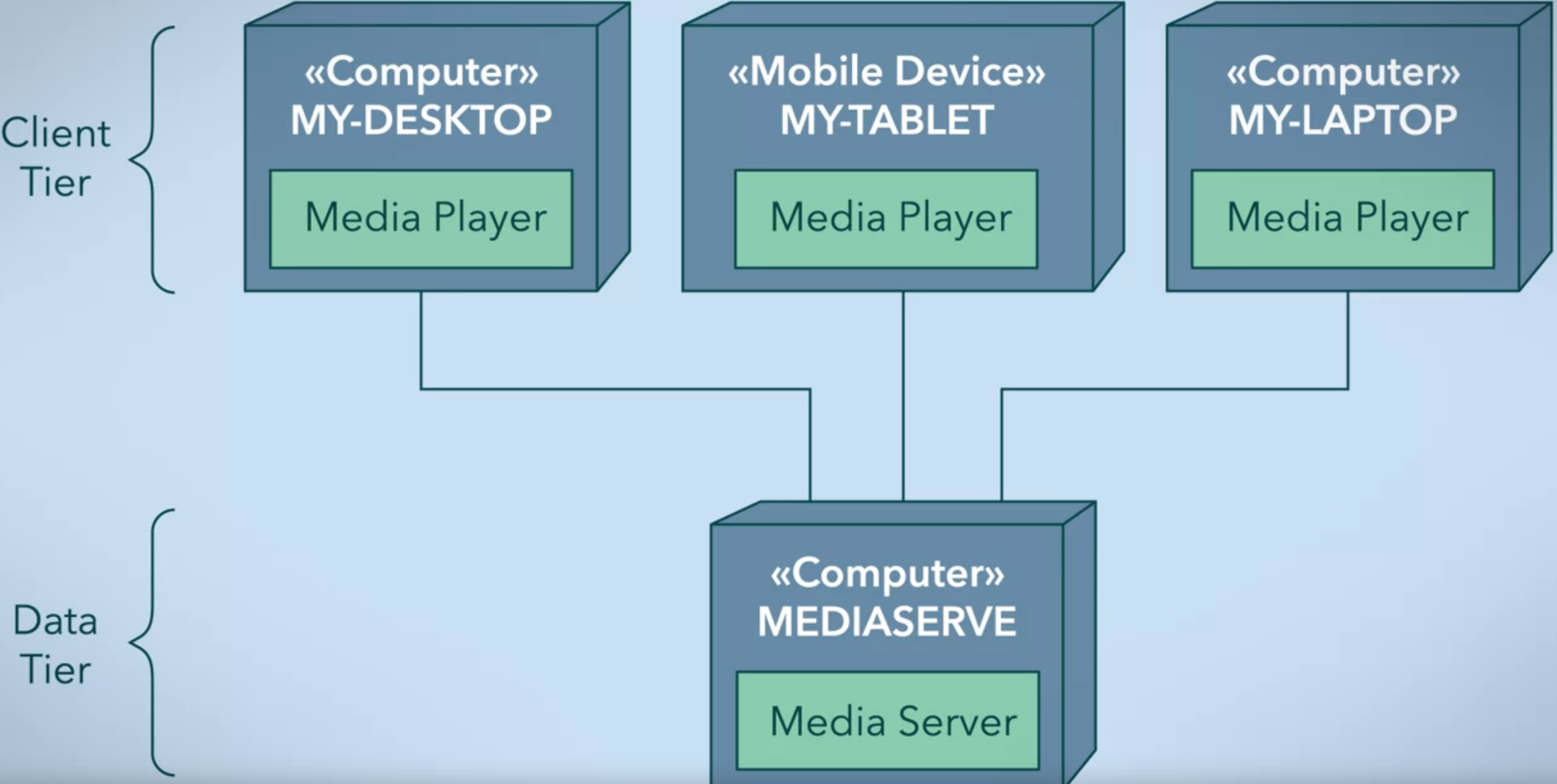
One computer hosts the media server process, where movies and TV shows are stored and can be streamed on demand. When a client requests a movie or TV show, the media server streams it to the client. Also, you can make a media server machine in one machine Desktop to play as a media player or media server.
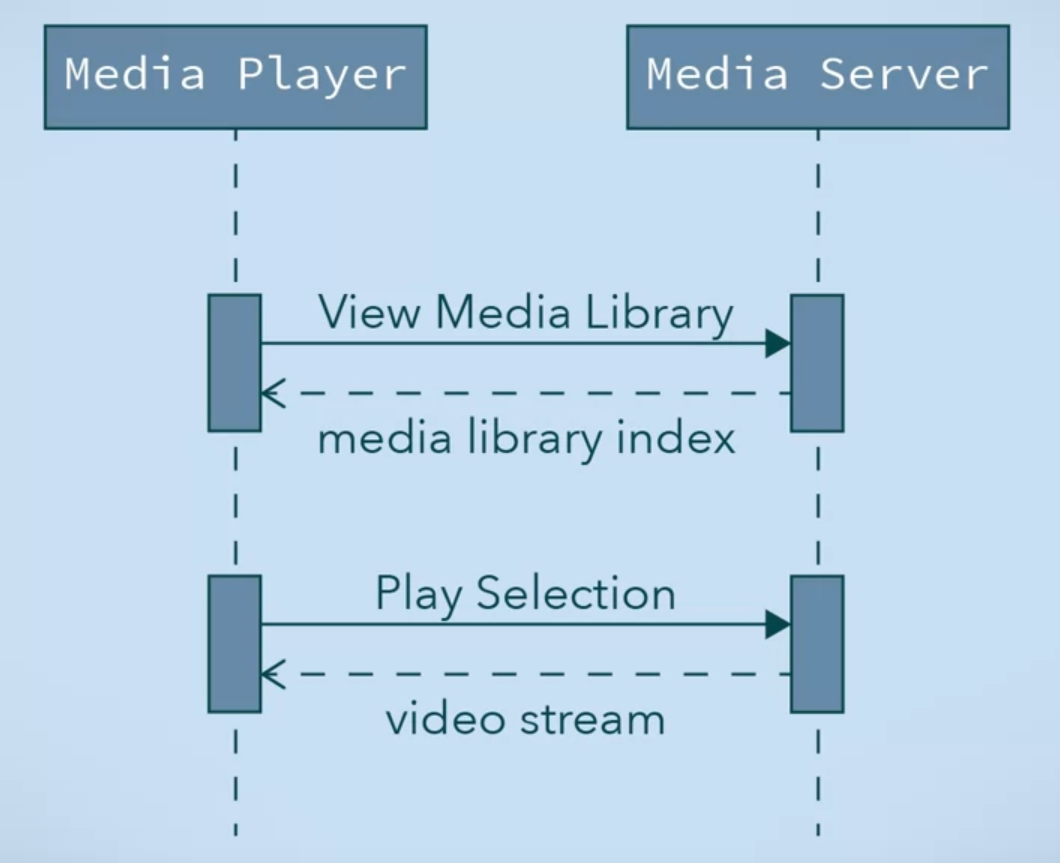
The above Sequence Diagram illustrates the Request-Response Messaging relationship. This relationship between client and server can be Synchronous or Asynchronous.
- In synchronous, the client sends a request then awaits the server’s response before continuing execution.
- In asynchronous, the client sends a request, but control returns right away so it can continue its processing on another need, so the processing not depends on server’s response. Once the server has completed the request, a message is sent to the client, which will have a handler to process the response. So it’s a better option.
Client-Host and Server-Host refer to machines that host the client and client software. There are many types of servers like Web Servers, Media Servers, Application Servers, File Servers, Data Servers, and Print servers.
Limiting client/server relationships to request/response messaging patterns allows for systems that can be scaled more easily by adding clients. Clients and servers are extensible, because as long as a server receives a message it knows, it will respond. The source of the message is not important to the server, so many clients can be added as needed.
Another example of 2-Tier Architecture
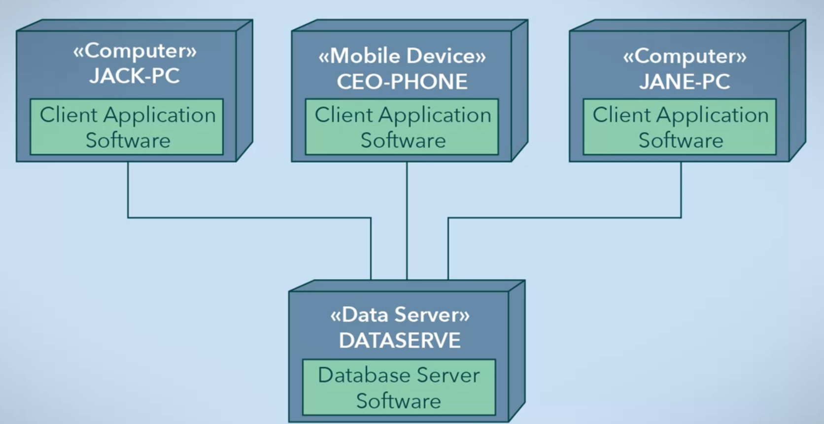
Problem: if the database changes, you are going to have to change the software on each and every computer. To make an improvement by inserting a tier in between data and end user to become 3-Tier Architecture.
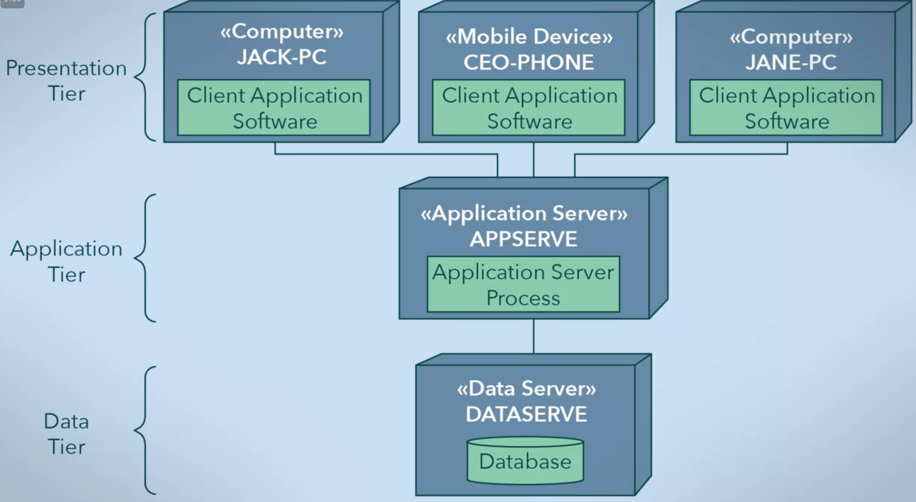
This layer has many names like Middle layer, Business layer or Application layer. It’s a client of the database and a server for the client application on the end users’ devices. It’s used to determine how and when data can be changed. So now the client software makes requests to the application tier, which makes data calls, so it’s easy to maintain.
N-tier architecture follows on separation of concerns, for the above example, the application logic could be split into security concerns and database operation concerns.
Drawbacks of the N-tier architecture.
- It demands extra resources to manage the client/server relationships, meaning adding more tiers means adding more machines to manage with different communication protocols between machines which makes the system more complex.
- A server acts as a central point of failure, Systems may have backups or mirrors, but it can take time to switch to these backups and recover the server. Redundant servers are possible but add complexity.
Advantages of the N-tier architecture.
- Very scalable. Clients can continue to be added as long as a server can handle all the requests it receives in a reasonable time.
- Centralization of functionality allows for data to reside on one machine but to be accessible by any machine on the same network.
- Centralization of computing power allows client machines to require less processing power. Companies can thus offer processing power as a service, which is more practical and cost effective.
- Supports separation of concerns. Middle layers can take the role of managing application logic and accessing the database directly. Adding tiers can further allow for more separation of concerns, loose coupling and levels of abstraction, making a system that is easier to change and extend.